structured cable management

Structured Cabling’s Six Subsystems – Part 2

28 Aug 2017

structured cable management,DCAs mentioned in Part 1, a structured cabling system is a type of open network structure that can be used by data, telephony, access control, building automation, and other systems. Its advantages are operational flexibility and economy. Part 2 will describe each of structured cabling's six subsystems below.


The Six Subsystems


1. Entrance Facilities


Entrance facilities house the protection devices, network demarcation points, cables,  connecting hardware, and other equipment that connect to private network cabling or the access provider. Connections between the inside building and outside plant cabling are included.


2. Equipment Room


Featuring environment control, the centralized area for telecommunications equipment is typically more complex than a telecommunications room. Usually containing the main cross-connect, it may also house the horizontal and intermediate cross-connects.


3. Backbone Cabling


Backbone cabling provides the interconnections between entrance facilities, telecommunications rooms, equipment rooms, etc. Typically, backbone cabling is comprised of fiber optic cables, intermediate and main cross-connects, mechanical terminations, and patch cables utilized for backbone-to-backbone cross-connections.


4. Telecommunications Room


Housing the terminations of backbone and horizontal cables to connecting hardware with patch cords or jumpers, a telecommunications room may also house the intermediate cross connects or main cross connect for different portions of the backbone cabling system. This space is a controlled environment containing telecommunications equipment, connecting hardware, and splice closures.


5. Horizontal Cabling


Extending from the work area’s telecommunications information outlet to the telecommunications room, the horizontal Network Cabling consists of horizontal cables and mechanical terminations, along with the jumpers and patch cords located in the telecommunications room. The system may also incorporate consolidation points and multi-user telecommunications outlet assemblies.


6. Work Area


The work area’s components typically extend from the telecommunications outlet/connector end of the horizontal cabling system to the work area equipment. At least two telecommunications outlets should be installed in every work area. If utilized, multi-user telecommunications outlet assemblies (MUTOAs) are a component of the work area.


Progressive Office Cabling


Founded in 1986, Progressive Office’s success has been a direct result of years of commitment to seeking solutions on behalf of their clients in the Washington, D.C. and New York City areas. Working together, their cabling teams get cabling installed and operating as fast as possible while minimizing disruption and downtime. Call their toll free number (800) 614-4560 today.

Structured cabling,Network Cabling, Washinton DC

Structured Cabling’s Six Subsystems – Part 1

22 Aug 2017

cable management,Network Cabling,Washinton DcA structured cabling system is a type of open network structure utilized by data, telephony, access control, building automation, and other systems. Its advantages are operational flexibility and economy. A structured cabling system is typically divided into these six subsystems: 1) Entrance Facilities, 2) Equipment Room, 3) Backbone Cabling, 4) Telecommunications Room, 5) Horizontal Cabling, and 6) Work Area.


Overview


Structured cabling is the design and installation of a cabling system that can provide support to several hardware use systems, and be suitable for both the needs of the present and the future.


Governed by international standards regarding the wiring of data centers, offices, and apartment buildings for data or voice communications, structured cabling design and installation utilizes several types of cable. These are typically CAT5e and CAT6, along with fiber optic cabling and modular connectors.


Defining methods and specifications for the laying of cabling in various topologies for meeting customer needs, standards typically require the use of a rack-mounted central patch panel from which modular connections can be used as required. Every outlet is then patched into a network switch for network usage or into a PBX (private branch exchange) or IP telephone system patch panel.


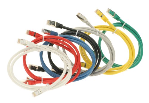
The use of color code patch panel cables is common for identifying the type of connection. However, it is not required by structured cabling standards with the exception of the demarcation wall field.


Cabling standards require that all eight conductors of CAT5e, CAT6, and CAT6A cable are connected to discourage "doubling-up" or the use of one cable for both data and voice. However, IP telephone systems are capable of running both telephone and the computer on the same wire.


When copper cabling, CAT5e, CAT6, or CAT6A is used, the maximum distance is 90 meters (98 yards) for the permanent link installation, along with an allowance of 10 meters (11 yards) for patch cords at the combined ends. Both CAT5e and CAT6 are capable of running Power over Ethernet (PoE) applications up to 90 meters. Due to power dissipation, CAT6A performs better and more efficiently.


Part 2 will summarize each of structured cabling's six subsystems.


Progressive Office Cabling


Founded in 1986, Progressive Office’s success has been a direct result of years of commitment to seeking solutions on behalf of their clients in the Washington, D.C. and New York City areas. Working together, their cabling teams get cabling installed and operating as fast as possible while minimizing disruption and downtime. Call their toll free number (800) 614-4560 today.

Structured Cabling,Washington DC New York City

Basics of Riser Cables

6 Mar 2015

Structured Cabling,Network Cabling Data Cabling Riser cables were designed for non-plenum vertical applications like between the floors of multi-story buildings. They are also described as backbone cables. These cables serve as the main conduit of a distribution system for data, video or voice. It originates from the point where communications go in through a particular edifice.  This cable comprises part of the structure backbone. Other components of this facility are the cable corridors, telecommunications cabinets, equipment rooms, correlated hardware, and support facilities. This cable variety must be fire resistant in accordance with electrical codes. Nonetheless, specifications are not as stringent compared to plenum cables.


Understand its Uses


Riser cables may be used for different forms of data communications which also includes CCTV video access. It is ideal as well for voice communications. One major concern is that requirements vary for each service. Hat is why planning can sometimes be quite complicated. Building managers are often pressed to predict their requirements given limited time and expertise. Quite often they will recommend creating split riser systems for multiple applications which follow parallel routes through the corridors, closets, and equipment areas.


How do you select the medium?


Perhaps, the primary concern is to stay within budget.  You can expect system designers to resort to trade-offs in delivering a broad assortment of services within the backbone system. Other factors that may influence their design are the following:


  • Provide an adaptable medium in relation to supported services

  • Identify the necessary useful life span of backbone cabling

  • Consider the technical needs of users


Standards are on hand to serve as a guide in the design of riser cable systems. There are appropriate benchmarks for optical and copper cable backbone structures. Some of the backbone cable categories include:


  • Copper-shielded and unshielded twisted-pair or UTP cables

  • Coaxial and twin axial cabling configurations

  • Single mode and micron multimode optical fibers


Physical locations supporting riser cables take into consideration the telecommunications service entrances and adjacent equipment rooms containing the main cross-connect. This can extend to the telecommunications closets that serve a particular location, intermediate cross-connects that serve a number of telecommunications closets, or horizontal cross-connects for a remote telecommunications closet or just one level of the building. The telecommunications cabinet is the point of interaction between backbone systems and parallel (same floor) wiring.


Riser cable systems in multiple-story buildings need to pass through equivalent closets making use of connecting conduits between the floors. Said design provides each floor access to the backbone and allows circuits to be distributed to all levels. The conduit and sleeves should go higher than the floor level by at least an inch and fitted with fire-stopping material. These should also adhere to electrical codes. The riser or backbone cable system essentially acts as the core of telecommunications infrastructure.


Network cabling, NetworkTopologies.

Essential Facts About Cabling System

14 Dec 2014

Network cabling, NetworkTopologies.Your office cabling system is costly and complicated investment. It's also a commitment to an office design and structure that is not easy to modify. If you add more workstations later, new cabling might be needed.


Most offices have a structured cabling topology that hardwires the cables from wallplate to patch panel. With this system, modifications are less likely because the initial installaiont includes a planning process that should anticipate some expansion. By pre-wiring potential locations in an existing or newly-constructed building, future moves, additions or alterations are avoided. You can just transfer patched cables in the wiring closet. Also, it is critical to number the wallplates to match the corresponding patch panel number. This will make it much easier to relocate a workstation or to troubleshoot a connectivity problem.


There are several sub-systems to consider:


  • The Demark refers to the point where the Internet Service Provider's (ISP) data line comes to an end and hooks up with the cabling in the building.

  • The equipment room serves as storage for all apparatus and wiring integration points.

  • Backbone cabling are high-speed cables (typically Cat6 or fiber) that connect various floors or wall closets.

  • The horizontal cabling for links up the network space to individual wallplates. These are done through conduits and ceiling spaces on every level.

  • The telecommunications enclosures are wall or floor mounted cages that hold the network equipment; primarily the patch panels ands switches but also sometimes the server and Uninterruptible Power Supplies (UPS) too.


Installation and design of structured cabling is regulated by standards that identify the following:


  • Network data switches

  • Offices layout for voice & data communications for Cat5e or Cat6 cable

  • Fiber Optic cables for backbones

  • Modular connectors at the wallplate


These components will guide the layout of cables in order to fulfill the data access requirements of your office. All of the cables start at the patch panel on a mounted rack (about 19 inches wide) in the wall closet. From there, they traverse through the drop ceiling and down the walls to individual wallplates. Quite often a wallplate will host 2 or more connections. At the wallplate a short patch cable, usually 7 to 14 feet in length wil connect the computer, phone, printer or other networked device.


All cabling standards require that all of the eight conductors in Cat5, Cat5e and Cat6 cables are inter-connected in a precise color-coded pattern. The network cable connects each device but some devices can share a single cable. This is true for VoIP phones. Most VoIP phones have a jack for the network cable and then a jack on the phone for connecting the computer. This pass-thru enables the two devices to share one connection.