Fiber Cabling Installation Washington DC

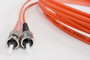
Why Cable Pros Select Fiber Optic Over Copper Cabling
29 Aug 2018

cable,cabling,installation ,Washington DCDuring your consideration of the kind of cable that should be selected for your IT network, several factors come into play. One of the decisions you will need to make is whether to use copper or fiber optic cabling.


Copper certainly has plusses. It is already installed in numerous sites and is less costly for connecting network components. Although fiber optic cabling has a higher price tag, it has key advantages that make it more attractive than copper for creating structured cabling infrastructure.


The following are five reasons why most cable professionals select fiber optic over copper cabling.


Durability


Fiber optic cables have longer service lives than copper, decreasing maintenance costs and downtimes from replacements. Although fiber optic wires are made of glass, copper wires are more susceptible to being damaged.


Fiber Optic is Faster


When evaluating the transmission of copper wire to that of fiber optic, the contest can be simplified to the comparison of the speed of electrons to the speed of photons. Although C transmissions do not move at the speed of light, they are still extremely fast by moving just 31% slower than the speed of light!


Low Attenuation


Over long distances, fiber optic cables will undergo much less signal loss than copper. This quality is termed “low attenuation.” Due to attenuation, copper cables are capable of transmitting information up to a maximum of 9,328 ft, when it then loses power. In contrast, fiber optic cables are capable of transmissions up to 24.8 miles.


Resistance to EMI (Electromagnetic Interference)


If improperly installed, copper cables will generate electromagnetic currents that result in EMI inside nearby wires, which can cause serious problems throughout a network. On the other hand, fiber optic cables are not conductors of electricity.


Safer


Fiber optic cabling is safer because it won’t be a fire hazard. The reason is no electrical current travels through fiber optic cables.


Progressive Office Cabling


Founded in 1986, Progressive Office’s success has been a direct result of years of commitment to seeking solutions on behalf of our clients in the Washington, D.C. and New York City areas. Efficiently working together, Progressive teams get cabling installed and operating as fast as possible while minimizing disruption and downtime. Call our toll free number (800) 614-4560 today.

Cable Management,Cable Management ,Data Cabling ,Cat5e, Cat6/6a Cabling

Overview of Cable Management Practices – Part 2

28 Mar 2017
Cable Management ,Data Cabling ,Cat5e, Cat6/6a Cabling

As mentioned in Part 1, the wired industry continues to grow despite the trend towards wireless communications during the past decade because of security concerns. Concrete trenching and floor decking were discussed as two of the four main practices of cable management. Part 2 will discuss Overhead Cabling/Cable Drops and Underfloor Cable Management. Consult with experienced professionals to make your cabling project a long-term success.


OVERHEAD CABLING/CABLE DROPS


Deployed within single-story and multi-story buildings, overhead cabling provides flexibility. This method uses overhead space, which can either be a dropped ceiling or an exposed ceiling. Cables and conduit are suspended from the ceiling, and cable drops, which are concealed by chaseways or poles, descend to serve work areas.


Advantages


This method does not require any cutting or trenching of concrete cutting. Unoccupied areas are used to install conduit and cabling.


Disadvantages


It will be a challenge to reroute cabling as technicians will need to use a ladder all along a line. Cable drops are generally considered an eyesore, and so this practice is highly discouraged for facilities that emphasize customer experience, such as retail. It may not be appropriate in the work areas of certain professions such as law offices.


UNDERFLOOR CABLE MANAGEMENT


Utilizing access flooring for the routing and concealment of cables, underfloor cable management may be the most advantageous. Cables can be routed beneath the flooring or within the floor itself in low-profile access flooring.


Advantages


Underfloor cable management does not require concrete cutting or trenching. It is not necessary to work inside ceiling space. There is flexibility in routing, and cable rerouting is easy. Low profile floors are only one to three inches in height. There is almost an unlimited number of possibilities for layout designs. It can be rapidly installed during construction, and business disruption is minimized whenever additions and changes need to be made.


Disadvantages


The method takes up space of one to three inches in height. There will be an extra step in the installation process.


Union Network Cabling


When union work requires a unionized cabling group, call on Union Network Cabling for your commercial Cat5e/6/6a and fiber cabling projects. Specializing in cabling for data, voice, security and even the latest WiFi and LiFi solutions. Phone: (202) 462-4290

structured cabling,Offie CAbling

Cable Network Trays as Support Systems

12 Jun 2015

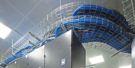
cable network trays, Data CablingCable trays for networks are support systems that can be mounted on walls or hang up from ceilings. The trays are fabricated from aluminum or steel. These come in deepness of 2, 3, 4 and 6 inches. There are also multiple designs like trough (single rail), ladder, basket, and wire-mesh. The single rail is designed either with single or several options.


Types of Trays


The solid bottom trays support delicate cables. On the other hand, the center spine model is made up of a central support mechanism supporting the cable with the tray dangling from rods. This tray is important to the data communications market. The single-rail variety mounted on the wall is similar to center-spine. However, the treads can be found only on one side. Wire way is a system that is fully enclosed and provides no access to cabling inside.


Locations where cabling trays are required as well as cable types these carry have evolved during the last two decades. Cable trays are installed not only in power plants and paper mills but also in government facilities, schools and call centers. Certain manufacturers supply product categories produced for installation with uncommon requirements. For instance, the cable tray should be very robust so it can link a span of 30 feet between support systems. The short span variety supports four to five feet or limited space requirements of newly-installed components. Problems are resolved by using different types of cable trays.


Product Selection


The key to this is careful product selection since a single tray will not fit into all requirements. This offers the perfect solution. The main consideration is there are various instruments in the tool box of cable trays. You only need to match up each application for the ideal solution. Right now, there is an increasing need for big-sized trays so it will be possible to add more able in the future.


Modern installations entail manufactured support systems that can effectively hold both Category 5 and 6 cables. While cable performance becomes more efficient, cable and connector makers are also offering warranties for their performance. Along this line, the appropriate cable tray is needed so that cable performance will not be adversely affected by improper cable management.


What are the Benefits?


Contemporary cable trays have multiple benefits. These include the capacity to carry heavy weights. Installation is also faster and less complicated with reduced fitting time. Fixtures like risers, reducers and bends may be built on site. The applications have also expanded to several sectors such as industrial, infrastructure, commercial, food, and data hubs.

Structured Cabling, Washington DC, New York City

Resolving Vital Issues in Network Cabling

5 Jun 2015

 Structured Cabling ,Washington DC New York CityThe quality of information flow is no better than the medium that carries it. This is the cabling network. The structured cabling platform will ensure that information flows efficiently through the cabling system. It consists of transmission tools applied according to standard engineering designs that enable users to transmit voice and data signals.


The controlled cabling system is the foundation and essential investment that provides a common, mutual platform for multiple information technology systems. However, there can be problems and information flow can be obstructed because of an information technology structure that has been designed improperly. Therefore, it is necessary to tackle crucial concerns in structured cabling during the planning stage.

Read More

Network Cabling ,Data Cabling, Cat5e ,Cat6/6a Cabling

Reviewing Tools for Cabling Installation

30 May 2015

 Network Cabling, Data Cabling, Cat5e,Cat6/6a CablingCabling installation requires a lot of expertise. This is important due to the complexity of networks cables for data and communication services.  There are tools installers use to install and test cables. Some of the instruments include carts and caddies.


Basic Implements


Network carts and caddies hold cable spools for easier pulling. Reels can be set up on the wire cart which can hold 500 and 1000 foot reels. Cables are mounted on bars that slip through bored holes on the mounting framework. The cart contains a large, wide base that prevents tipping when you pull the cable.  Wire caddies secure smaller cable spools which come in lengths of 500 feet or less. And it has dividers that prevent the wires from becoming crisscrossed and twisteded.


Termination Tools


The appropriate termination tool increases productivity. It allows installation and termination of Cat5e and Cat6 jacks onto the connectors on a patch panel.


This "punch down tool" ensures accuracy and consistency. There are three categories: manual, impact and multi-wire. Cable installers can opt for a manual but most consider the impact tool to be the best option.


The fundamental impact instrument is fitted with a spring-loaded head which can be triggered by the installer. Not much force is needed. The spring is released automatically after being compressed. Modern multi-wire tools like the Jack Rapid punch down tool can terminate jacks eight times faster.


You can use several interchangeable blades for various impact tools. However, this depends on your cabling system. The advantages of this tool are its speed, user-friendliness and uniformity of termination. Sophisticated models consist of fixed blades that cut off leftover wire instantly instead of having to use wire cutters. These new products include a handle that is easy to hold, a disposable blade head and fixed band that holds the jack in place.


Other Useful Tools


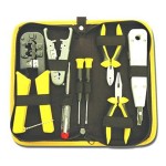
You might need professional shears to ensure a quick, clean, and accurate cut.  Each job requires cutting of cables and trimming of excess wires.  A premium cable stripper guarantees immediate and hassle-free elimination of exterior insulation from multi-core cables, unshielded twisted as well as shielded twisted pairs. The flexible depth gauge will give better results.  Refrain from using pocket knives or ordinary scissors because you will probably end up damaging the cable. Other functional tools for cable installation are can wrenches for demarcation point boxes; crimping pliers; knives for splicing cables; voltage detectors; modular plug crimpers for telephones; and, probe picks to detect loose or broken connections.


But if you prefer to have a profession all do it all for you, contact us!

Network Cabling ,Data Cabling

What is “Alien Crosstalk”?

8 Mar 2013

 Network Cabling, Data CablingNo, it’s not ET calling home. “Alien Crosstalk” is defined as “unwanted signal coupling from one balanced twisted-pair component, channel, or permanent link to another”.


Alien crosstalk is not generally affected by common noise from motors, transformers, or florescent lighting fixtures. Alien crosstalk is specified as “a parameter for cabling to approximate the energy present when all cabling pairs are energized”.

Read More