Data Cabling,Network Cabling, Washington DC

Introduction to Network Cabling – Part 1

12 Jun 2017

 Data Cabling,Network Cabling, Washington DCCabling utilized for network infrastructure is a crucial aspect of networking, and it has grown in importance as new technologies are introduced, including virtualization, wireless access points, blade servers, network storage devices, etc.


Although wireless technology has greatly advanced, most of the existing computer networks are still using cables as the media for transferring data. Each standardized type of network cable is utilized for a specific purpose as discussed below.


Coaxial Cables


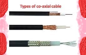
Patented in 1880 (yes, that long ago!), coaxial cable is most familiar as the cable that connects TV sets to their antennas and also as the standard for 10 Mbps Ethernet, which was common in the 1980s and early 1990s. During this time, networks utilized two coaxial cable types, thicknet, the 10BASE5 standard, or thinnet, the 10BASE2 standard. Composed of an inner copper wire surrounded by insulation and shielding, the stiff quality of these cables made them difficult to install and maintain.


Twisted Pair Cables


During the 1970s, Ethernet was developed at Xerox, which began collaborating with Intel and DEC for its standardization. The initial specifications, titled the Ethernet Blue Book or DIX from their three company initials, was published in 1980.


In the 1990s, twisted pair cables became the primary cabling standard of Ethernet, beginning at 10 Mbps with Category 3 or Cat3, which was followed by 100 Mbps Cat5 and Cat5e and up to 10 Gbps (10GBASE-T). Ranging up to eight wires wound together in pairs, this type of cabling is intended to minimize electromagnetic interference.


Unshielded Twisted Pair (UTP) and Shielded Twisted Pair (STP) are the two chief twisted pair cable types standardized by the industry. Due to lower manufacturing costs, modern Ethernet cables utilize UTP wiring. STP cabling is used by other types of networks like Fiber Distributed Data Interface (FDDI). Clearly the most common network cable type globally, UTP cable is utilized for both networking and for the traditional telephone (UTP-CAT1) cabling.


UTP-CAT5e or Cat5e has become the most common UTP cable as it replaced coaxial cable, which was unable to cope with the increasing demand for networks that were faster and more reliable.


Part 2 will cover Fiber Optics, USB Cables, and Crossover Cables.


Union Network Cabling


When  your work requires a unionized cabling group, call on Progressive Office Inc. for your commercial Cat5e/6/6a and fiber cabling projects. Specializing in cabling for data, voice, security and even the latest WiFi and LiFi solutions. Phone: (202) 462-4290

Directions in Telecommunications and Cabling

3 Apr 2015

 Data Cabling ,Network cabling, DCThe telecommunications industry continues to advance. And bandwidth demands will continue to increase. Meanwhile, conditions to convey considerable amounts of information quickly are changing. Applications including graphic information, technical modeling, video conferencing, and multi-level online databases will certainly increase bandwidth requisites. The bottom line is demand for higher transfer speed for information is expected to rise.


Properties for Cabling Systems


Two principal properties needed for cabling systems are performance and easy installation. Fiber and shielded twisted-pair provide stronger signals compared to Unshielded Twisted Pair (UTP) although these two lagging in client acceptance. The question is will UTP provide the appropriate bandwidth for modern applications?


Unshielded Twisted Pair


UTP is considered the most prevalent cable worldwide for telecommunications and networking. Cat 5e is the most popular and it long ago replaced coaxial cable which failed to keep up with more dependable and faster networks. UTP is also easy to install, develop and troubleshoot. Unshielded Twisted Pair cabling does not have any foil covering. It depends on twisted pairs inside the cable to prevent electromagnetic interference. UTP is used extensively for local area networking and comparable cabling configurations. Hence, installation is easier and less expensive.


Shielded Twisted Pair


Shielded twisted Pair (STP) features a metallic foil enclosing twisted wire pairs inside the cable. This is the safeguard against electromagnetic intervention which facilitates rapid data transmission. STP functions by drawing electromagnetic interference and counterbalancing this with grounded cabling. The drawback is that if the cable is not grounded correctly it loses the capacity to prevent unnecessary noise. STP is also larger and more sensitive compared to UTP cables. Expert cable installers use this cabling for industrial environments where adjacent equipment emit significant amounts of elctron-magnetic interference (EMI). Actually, UTP and STP can perform well if installed and maintained by efficient cabling providers.


Transmission is Essential


Transmission should be balanced. This is the standard for conduction of data using twisted cabling pairs. Separate protection for balanced twisted pairs is designed to enhance resistance and emission of the communication lines. The shielding method produces a conductive barrier that lessens these electromagnetic waves. It also creates a conduit for conduction so that currents and can pass data through without any obstruction. Shielding can be performed on individual pairs or as one set of pairs.


Please contact us if you have any questions or concerns or if you need a free quote on your cabling project.


Network Cabling Data Cabling Cat5e Cat6/6a Cabling

Cabling Tips for Security Cameras

11 Nov 2023

CablingNetwork Cabling, Data Cabling, Cat5e, Cat6/6a Cabling,security system is definitely not the showy part of any security system. Nevertheless, it is an essential component of the system. It may seem complicated. There are many considerations in choosing and installing cables to ensure that the security system functions properly. Cables basically provide power for camera installation and transmit signals going back to the digital video recorder (DVR).


Deciding on the Perfect Cabling


Find out whether the system is analog (alternating current frequency has been modified) or digital (electronic technology). Then, you can figure out the proper cable for installation of your security cameras. Or simply refer to the manufacturing specs on the camera system.


The second step is to determine if your camera is powered remotely or connected to a nearby power outlet. It may be necessary to combine power and video cables. Security power and video cables can run next to each other or within one cable jacket. This makes installation easier by pulling one instead of two separate wires.


Make sure to test the cable before you install the CCTV. Examine each cable at the DVR position just to make sure that the cables are working prior to installation.


Cabling Guidelines


Quite often security cameras require coaxial cables to send video from the camera to your recorder. With the RG59 type of coax cable, it is possible to position the camera up to 600 feet away. The RG6 coax cable, on the other hand, may be extended up to 1,000 feet. Cut the cable according to your preferred length but leave an extra service loop of 10 – 20 feet for future flexibility.


What are the steps to follow?


  • Make the necessary BNC connection on the cable. This is a small quick round connector primarily for coaxial cables.

  • Plug one end of the BNC cable to the camera and the other to your DVR.

  • Strip the shield of the power cable to expose the black and red wires. Then, remove the jacket (at least ¼ inch) from each wire.

  • Put the wires inside the terminal block at the end of the female power wire plait. It should be red on red wires and black on black wires. Tighten screws on the terminals. Plug the camera into the fitting at the side of the braid.

  • Attach wires directly to the positive and negative leads respectively in the power box. Red wire is for positive while black is for negative. This is applicable if you will connect the camera to a multiple camera power supply unit.

  • In case you will attach the camera to a single power unit, connect the male power wire braid as well as power supply to the tip of the tress.


Now, the installation is complete and you are ready to use the system.