structured cabling, Data Cabling, cabling tester

Facts about Data Cable Testing

6 May 2015

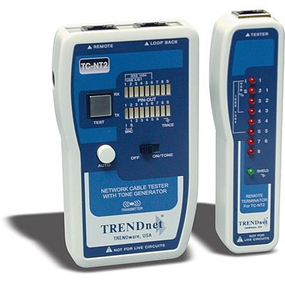
structured cabling, Data Cabling,  cabling testerTesting always plays a vital role in the process of installing new cables or servicing existing ones. Regular testers for data cabling include length, wire crimper map, attenuation, return loss, and DC loop resistance.


Complex Cabling Needs


Cabling infrastructure requirements have become more complicated. More standards are being developed for cabling professionals in testing and troubleshooting copper and fiber cables. And there are special requirements as well as downsides in the implementation of new  technologies. From 10BASE-T to 100BASE-TX to 1000BASE-T and now to 10GBASE-T. It is now more crucial to keep in step with the most up-to-date techniques in cable testing too. In short, cable testing infuses a higher degree of assurance that installed cable links will attain the preferred transmission capacity for your data communications.


Cabling Tester Categories


Cable testing instruments have been manufactured with unique features for specific tasks. Costs, performance, and applications vary. These depend on the required functions. The three main functions are certification, qualification and verification. Although certain attributes overlap, each category answers a particular testing prerequisite.


Certification facilitates conformity to standards defines by the industry. These are instruments signal a “Pass” or “Fail” towards data testing compliance within standardized industry norms. These testing instruments will find out whether a cable link conforms to a category or class such as Cat6 or Cat5e. It is the last step required by most structured cabling installers towards approval of a new  installation.


Qualification determines if the existing cable is capable of supporting specific network speeds. This special class of testers is supposed to meet the up-and-coming requirements of network technicians who troubleshoot data networks. These testers perform checks to make a decision on whether a present cable link supports the requirements for fast or gigabit Ethernet. With these instruments, network technicians can identify and isolate cabling issues. While Continuity testers do not perform the series of tests set down by these standards and are not  considered certification tools.


Verification makes sure that cabling connections are correct. This type of tool performs a continuity test. It guarantees all wires in the cabling link have been attached properly to termination points at each end. For twisted pair cabling, there is an appropriate pairing of the wires. Such testing tools also confirm wire pairing and find out installation flaws such as split pairs. These can also help in troubleshooting by working with a toner to pinpoint a certain cabling link. These testing tools do not give out any information regarding bandwidth and data integrity.


If you need your cabling tested or certified, contact us!

Directions in Telecommunications and Cabling

3 Apr 2015

 Data Cabling ,Network cabling, DCThe telecommunications industry continues to advance. And bandwidth demands will continue to increase. Meanwhile, conditions to convey considerable amounts of information quickly are changing. Applications including graphic information, technical modeling, video conferencing, and multi-level online databases will certainly increase bandwidth requisites. The bottom line is demand for higher transfer speed for information is expected to rise.


Properties for Cabling Systems


Two principal properties needed for cabling systems are performance and easy installation. Fiber and shielded twisted-pair provide stronger signals compared to Unshielded Twisted Pair (UTP) although these two lagging in client acceptance. The question is will UTP provide the appropriate bandwidth for modern applications?


Unshielded Twisted Pair


UTP is considered the most prevalent cable worldwide for telecommunications and networking. Cat 5e is the most popular and it long ago replaced coaxial cable which failed to keep up with more dependable and faster networks. UTP is also easy to install, develop and troubleshoot. Unshielded Twisted Pair cabling does not have any foil covering. It depends on twisted pairs inside the cable to prevent electromagnetic interference. UTP is used extensively for local area networking and comparable cabling configurations. Hence, installation is easier and less expensive.


Shielded Twisted Pair


Shielded twisted Pair (STP) features a metallic foil enclosing twisted wire pairs inside the cable. This is the safeguard against electromagnetic intervention which facilitates rapid data transmission. STP functions by drawing electromagnetic interference and counterbalancing this with grounded cabling. The drawback is that if the cable is not grounded correctly it loses the capacity to prevent unnecessary noise. STP is also larger and more sensitive compared to UTP cables. Expert cable installers use this cabling for industrial environments where adjacent equipment emit significant amounts of elctron-magnetic interference (EMI). Actually, UTP and STP can perform well if installed and maintained by efficient cabling providers.


Transmission is Essential


Transmission should be balanced. This is the standard for conduction of data using twisted cabling pairs. Separate protection for balanced twisted pairs is designed to enhance resistance and emission of the communication lines. The shielding method produces a conductive barrier that lessens these electromagnetic waves. It also creates a conduit for conduction so that currents and can pass data through without any obstruction. Shielding can be performed on individual pairs or as one set of pairs.


Please contact us if you have any questions or concerns or if you need a free quote on your cabling project.


networ cabling,cable management

Things to Avoid in Running Network Cabling

28 Mar 2015

Date cabling,cable managementWhat can cabling that has not been installed properly do?


It can lead to a lot of negative outcomes such as paralyzed network performance, maintenance troubles and hidden costs. Network cabling can be  especially troublesome if it is installed by individuals without the proper knowledge and tools. When it comes to twisted pair cabling, there are many factors that you need to consider.


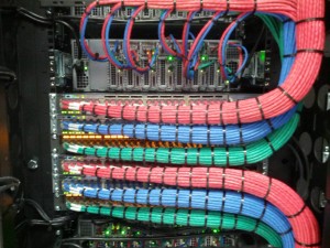
In the past, many companies installed different cable systems since twisted pair cabling was expensive. At present, full installation is still costly although a greater part of the expense is labor since raw cables is not pricey. Cable management is another concern. Use of ladder racks means additional cost but it reduces upkeep. Also be sure you label cables and to make use of color codes.


Unshielded twisted pairs are more practical in terms of usage. Magnetic fields are produced by low voltages that pass through your cables. This is a vital property of the communications cycle. And if you run unshielded cables along with electrical wires, the magnetic field can be interrupted. The communications becomes corrupted or noisy. You can expect that transmissions will not make it from one point to the other. Another possibility is that transmission rates will become slower. The cables should be perpendicular with electrical lines instead with the electric wires inside of shielded tubes at cross points.


Do not attempt to run cable alongside fixtures that create “noise”. Fluorescent lamps, motors and devices that generate electrical or magnetic interference will distort your cabling infrastructure. Install a data cable conduit that will create a buffer from these hazards. Also figure out the total distance of each cable. This is usually up to 100 meters. However, if cabling data rates reaches 10 to 40 GBPs, be attentive about distance restrictions related to the kind of cabling you plan to use. If you will run 10 GBPs for a maximum of 100 meters over twisted pair cabling, it is best to use Category 6 cabling.


Be aware of local codes.


This is important for safety concerns. In many areas, using PVC-covered cables is not allowed in air-handling spaces. When PVC burns, there is toxic emission that may prove dangerous to firefighters and other safety personnel who will try to navigate the location during emergencies. Failure to follow rules can lead to fines and forced replacement of cabling infrastructure. Contractors must be mindful of these regulatory standards.

Cat5e ,Cat6/6a Cabling,patch cables

Patch Cables and Twisted Pair Cabling

21 Mar 2015

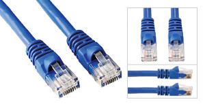
The patch cable is used to link up two network devices. This type of cabling is usually a Cat6 or a Cat5e cable thaCat5e ,Cat6/6a Cabling,patch cablest connects personal computers to the wall plate or provides the short interconnects among the switches, routers and the patch panels in the wall closet or Server Room. These make use of stranded wires instead of solid to increase flexibility. It also lessens the risk of cracking when you unplug the cable. There is also a variety of Ethernet patch called the crossover cable. It is used to hook up two PCs together and sometimes to interconnect switches.


Ethernet Systems


Ethernet systems ensure adaptable and economical methods of conveying voice, data, and multimedia over integrated networks. In fact, Ethernet patch cords have become very common. These wall to wall cables gave rise to the growth of generic and structured cabling systems. Today, these are used practically for all networking components regardless of industry or application. However, there are concerns that you need to consider. Whereas modular attributes and profusion of patch cables denote absolute universal use, there are differences that can reduce interchangeability. Some of the disparities originate from various wiring configurations of cable conductors and connector pins.


Twister Pair Cables


For this type of cabling, two conductors are coiled to prevent electromagnetic interference (commonly known as EMI) that comes from external (usually electrical) sources. One example is the electromagnetic radiation caused by uncovered twisted pair cables or UTP as well as cross talk produced by adjacent electrical wires. The process of shielding generates a conductive barrier to lessen these electromagnetic waves. It also creates a conduit for conduction so that  currents and data can traverse freely. Shielding can be applied on individual pairs or as a group of pairs.


Twisted conductor pairs form a secure circuit. The voltages carry the same magnitude or amplitude. However, one is positive while the other is negative. Incidentally, crosstalk takes place if the electromagnetic field turns out a signal that is too big or strong and intereferes with a nearby pair. The sound is like a fusion of the two fields by means of a swap of the energy between them. Certain components of these signals are passed on to each other during this exchange of energy.


As a result, here is an ensuing increase in the level of “noise”. External sources of EMI and RFI create signal interference in a similar manner. These cause distortion of the signals that go to your office and communications equipment.


Overall, these are the things that you should take into account with regards to twisted and patch cabling.


Please feel free to contact us if you need help with your office cabling project!

Network Cabling Data Cabling Cat5e Cat6/6a Cabling

Cabling Tips for Security Cameras

11 Nov 2023

CablingNetwork Cabling, Data Cabling, Cat5e, Cat6/6a Cabling,security system is definitely not the showy part of any security system. Nevertheless, it is an essential component of the system. It may seem complicated. There are many considerations in choosing and installing cables to ensure that the security system functions properly. Cables basically provide power for camera installation and transmit signals going back to the digital video recorder (DVR).


Deciding on the Perfect Cabling


Find out whether the system is analog (alternating current frequency has been modified) or digital (electronic technology). Then, you can figure out the proper cable for installation of your security cameras. Or simply refer to the manufacturing specs on the camera system.


The second step is to determine if your camera is powered remotely or connected to a nearby power outlet. It may be necessary to combine power and video cables. Security power and video cables can run next to each other or within one cable jacket. This makes installation easier by pulling one instead of two separate wires.


Make sure to test the cable before you install the CCTV. Examine each cable at the DVR position just to make sure that the cables are working prior to installation.


Cabling Guidelines


Quite often security cameras require coaxial cables to send video from the camera to your recorder. With the RG59 type of coax cable, it is possible to position the camera up to 600 feet away. The RG6 coax cable, on the other hand, may be extended up to 1,000 feet. Cut the cable according to your preferred length but leave an extra service loop of 10 – 20 feet for future flexibility.


What are the steps to follow?


  • Make the necessary BNC connection on the cable. This is a small quick round connector primarily for coaxial cables.

  • Plug one end of the BNC cable to the camera and the other to your DVR.

  • Strip the shield of the power cable to expose the black and red wires. Then, remove the jacket (at least ¼ inch) from each wire.

  • Put the wires inside the terminal block at the end of the female power wire plait. It should be red on red wires and black on black wires. Tighten screws on the terminals. Plug the camera into the fitting at the side of the braid.

  • Attach wires directly to the positive and negative leads respectively in the power box. Red wire is for positive while black is for negative. This is applicable if you will connect the camera to a multiple camera power supply unit.

  • In case you will attach the camera to a single power unit, connect the male power wire braid as well as power supply to the tip of the tress.


Now, the installation is complete and you are ready to use the system.


Structured Cabling,Washington DC New York City

Basics of Riser Cables

6 Mar 2015

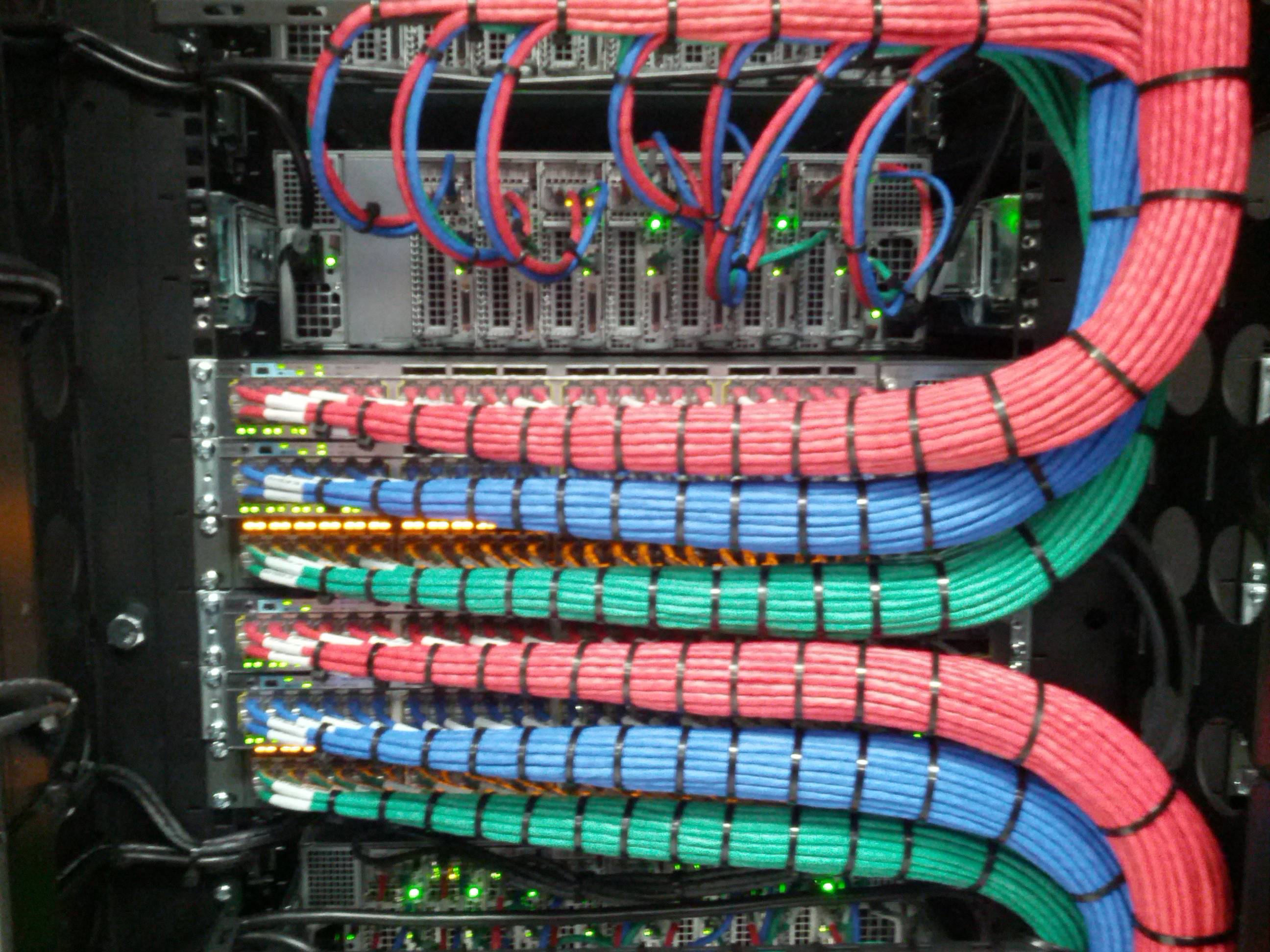
Structured Cabling,Network Cabling Data Cabling Riser cables were designed for non-plenum vertical applications like between the floors of multi-story buildings. They are also described as backbone cables. These cables serve as the main conduit of a distribution system for data, video or voice. It originates from the point where communications go in through a particular edifice.  This cable comprises part of the structure backbone. Other components of this facility are the cable corridors, telecommunications cabinets, equipment rooms, correlated hardware, and support facilities. This cable variety must be fire resistant in accordance with electrical codes. Nonetheless, specifications are not as stringent compared to plenum cables.


Understand its Uses


Riser cables may be used for different forms of data communications which also includes CCTV video access. It is ideal as well for voice communications. One major concern is that requirements vary for each service. Hat is why planning can sometimes be quite complicated. Building managers are often pressed to predict their requirements given limited time and expertise. Quite often they will recommend creating split riser systems for multiple applications which follow parallel routes through the corridors, closets, and equipment areas.


How do you select the medium?


Perhaps, the primary concern is to stay within budget.  You can expect system designers to resort to trade-offs in delivering a broad assortment of services within the backbone system. Other factors that may influence their design are the following:


  • Provide an adaptable medium in relation to supported services

  • Identify the necessary useful life span of backbone cabling

  • Consider the technical needs of users


Standards are on hand to serve as a guide in the design of riser cable systems. There are appropriate benchmarks for optical and copper cable backbone structures. Some of the backbone cable categories include:


  • Copper-shielded and unshielded twisted-pair or UTP cables

  • Coaxial and twin axial cabling configurations

  • Single mode and micron multimode optical fibers


Physical locations supporting riser cables take into consideration the telecommunications service entrances and adjacent equipment rooms containing the main cross-connect. This can extend to the telecommunications closets that serve a particular location, intermediate cross-connects that serve a number of telecommunications closets, or horizontal cross-connects for a remote telecommunications closet or just one level of the building. The telecommunications cabinet is the point of interaction between backbone systems and parallel (same floor) wiring.


Riser cable systems in multiple-story buildings need to pass through equivalent closets making use of connecting conduits between the floors. Said design provides each floor access to the backbone and allows circuits to be distributed to all levels. The conduit and sleeves should go higher than the floor level by at least an inch and fitted with fire-stopping material. These should also adhere to electrical codes. The riser or backbone cable system essentially acts as the core of telecommunications infrastructure.


Data Cabling,Structured Cabling, Cabling Design-Washington DC

Things to Avoid in Running Network Cabling

28 Feb 2015

What can cabling that has not been installed properly do?


network cabling,Data CablingIt can lead to a lot of negative outcomes such as paralyzed network performance, maintenance troubles and hidden costs. Network cabling can be  especially troublesome if it is installed by individuals without the proper knowledge and tools. When it comes to twisted pair cabling, there are many factors that you need to consider.


In the past, many companies installed different cable systems since twisted pair cabling was expensive. At present, full installation is still costly although a greater part of the expense is labor since raw cables is not pricey. Cable management is another concern.

Read More

Network Cabling ,Data Cabling,CAT2 6A UTP

Issues to Avoid with Cat6a Cables

22 Dec 2014
Network Cabling ,Data Cabling,CAT2 6A UTPA newly popularized cable is Cat6a. It is the new “cable on the block” which has prolonged the life of copper cabling. Cat6a has the shielded twisted and untwisted pairs with different advantages and features. It supports Gigabit Ethernet up to a hundred meters. However, you need to understand and cope with several issues.

Contentions


The size of Cat6a cable is larger than Cat5e. Copper is inherently unreliable due to Bit Error Rates or BER. This is why manufacturers have designed Cat6a cables with a smaller cross-section. It takes up less space in the tray. Yet, this space is needed to minimize crosstalk between cabling pairs. The protective shield in Cat6a cable adds to the expense.

Electricity and Mechanical Facets


Aside from the electrical issues, Cat6a Untwisted Pair (UTP) is fabricated with bigger conductors. It has more rigid twists compared to Cat5e and Cat6 and these heavier conductors plus large and stiffer jacket combines to make for more difficult cable installation. Besides, the external diameter of the UTP means that the Cat6a cable takes up more room in the trays and conduits.

Electrical and mechanical issues should not be overlooked since this can affect performance. The physical stability of Cat6a is essential to its transmission performance. Cat6a can be more sensitive to degradation of signal compared to Cat5.

These may be produced by the following:


  • Cable twisting generates signal reflection.

  • Excess insertion pressure on cables can cause poor connector performance.

  • Weakness of RJ45 (communications) connectors.


For example, if the cable is wedged in a door or compressed or squeezed by a heavy object, can result in sporadic network problems which may not be easy to detect. Nevertheless, Cat6a functions at enhanced specifications compared to Cat6 UTP. Considering all of these issues it may seem that fiber cable will become the ultimate future for 10 Gigabit Ethernet. It is up to users and the market forces to make the choice.
Network cabling, cables,shielding

About Ethernet Cables and Data Shielding

7 Dec 2014

Network cabling, cables,shieldingThe Ethernet network cable connects devices on a LAN (local area network) such as personal computers, switches and routers. These cables are typically Cat5 and Cat6. These cables provide the infrastructure that connects the PCs, printers, router/modem and other peripherals to a switch. The cables are made up of stranded or solid copper wires. Stranded wires are not as susceptible to fractures but are more difficult to terminate. Solid Cat5/Cat6 also is less susceptible to electrical interference. These shielded cables are made up of braided strands of copper wrapped in a polymer layer and spiral copper tape. The shield is applied across the splices.


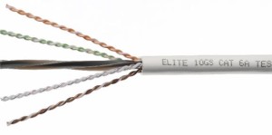
An Ethernet cable can be compared to an electrical power cord in that it can only extend a limited distances because of the electrical transmission properties. Meanwhile, wireless technologies (Bluetooth and Wi-Fi or local wireless technology) have enhanced the reach of Ethernet in residential and enterprise networks. The standard Ethernet cable consists of four coiled pairs that terminate at the eight pins of the clipped connector or "RJ45" at both ends of  a cable. At the wallplate is simply the female end of the same connector. The cable is made up of unshielded (UTP) or shielded twisted-pair (STP) cabling.


Shielding is not selected automatically during installations. The answer is, it affords the protection required for certain environments although there are also some downsides. One is mass. The single-shielded cable made of Ethernet weighs approximately 12 percent more than the unshielded cable. The double-shielded version is roughly 30 percent heavier. You may be putting together dozens or perhaps hundreds of individual shielded twisted-pair cables along  a  ladders tray above the ceiling, under a floor, or at the back of panels. The aggregate weight of these cables can collapse the mounting bracket.


Cable flexibility is also an important issue. Take care when you pull the cables through  conduits. The cable shielding can make installation more difficult. The sole foil shield can crack while the sharp boundaries of the shield can scrape the insulation of individual wires. This can cut the wire and cause data transmission issues.


What are the shielding options?


You have a number of shielding choices in for your Ethernet network. The single-shielded cable has the lightest protection. Double-shielded cables contain a foil and plate shield. It can ensure better protection against electromagnetic or radio frequency interference and reduce issues related to cable relocation. High-flex industrial cables are fabricated and protected for uninterrupted applications. These have special jacket materials to address industrial and outdoor concerns.

Network Cabling, Data Cabling

Bad Connectors will Kill your Network

3 Jul 2014

A client was having serious connectivity and network issues. It was a very small business with just a few computers. But as they were working, a couple of the machines were losing their connection to the Internet. The problems and symptoms had been going on for over a year. They would lose Internet connection and they figured out that if they unplugged and replugged the network cable that the connectivity would usually come back. But sometimes, they would have to unplug and plug a few times to get connected. As you could imagine, this was incredibly frustrating for them.


Fortunately, we found and fixed the problem very quickly.


When network connections are flaky we always first look at the cabling and then the hardware and software. And since this was a network-wide problem, we had a strong feeling that they either had a cabling issue or a bad network switch.


In Figure 1, we took a photo of the connector that was going into the modem/router. If you look closely, you can see that the sleeve ends just short of the connector. This is so wrong. The sleeve needs to go inside of the connector so that it provides support and strain-relief to the 4 twisted pairs of wires. The wires would get bent at 90 degrees which changes the impedance and properties of the signal. Figure 2 is the inside of one of the wallplates. As you can see, the wires are untwisted and then punched into the slots for each of the 4-pairs. But they are untwisted too much.There should be no slack in between the sleeve and the connections. So, again, this will greatly reduce the effectiveness of the data transmission.


All cable connections and wallplates were checked and fixed. We cut off the bad connectors and recrimped on new ones. And we reterminated the wallplate. Since then, they have had 100% uptime on the Internet Service.


Are you having network cabling issues? Call 202-462-4290 or click here to contact us.